Lab 05 Arduino Programming
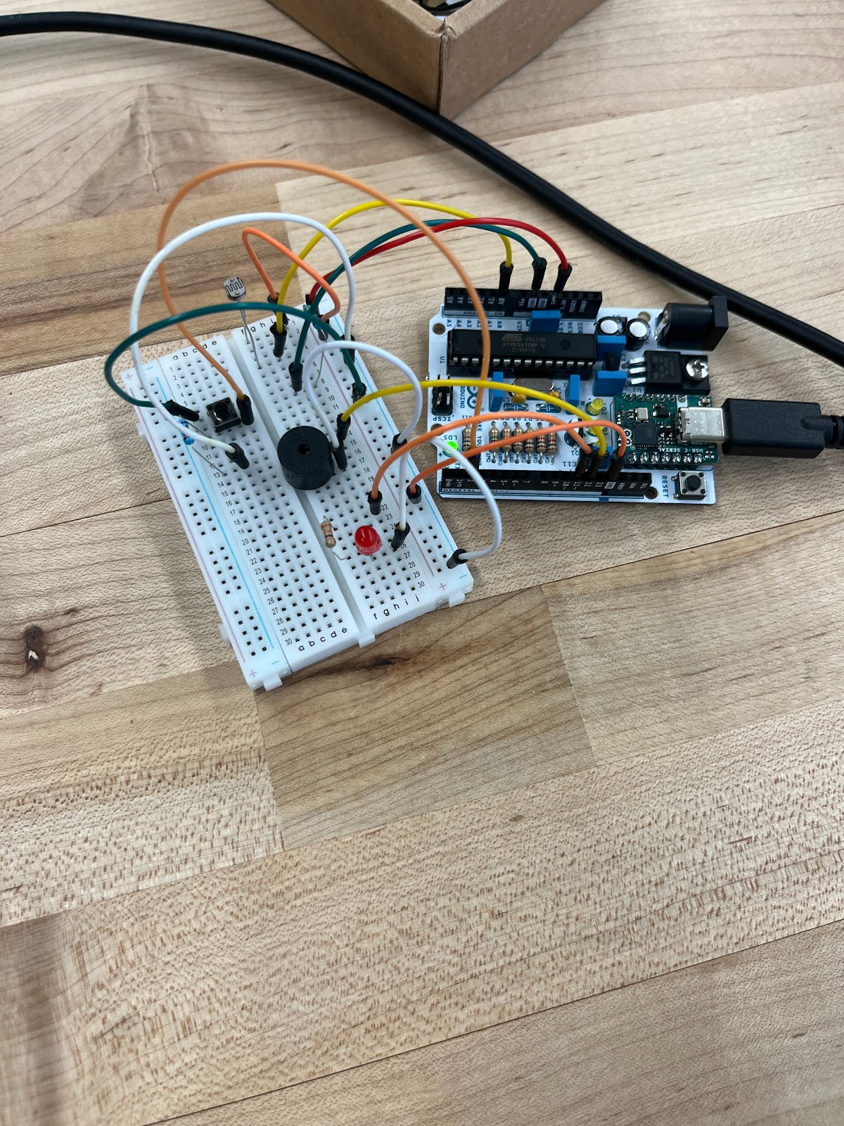
After gaining a base familiarity with Arduino in the previous lab, the next task was to create a circuit and program to turn on a light and play a tune. This circuit was a bit more complicated than the previous lab, as it involved two different inputs (photosensor and button) and two different outputs (piezo buzzer and LED). Because there were several components that required 5 volts DC and ground, I made use of the vertical bus bar on the side of the breadboard, connecting 5 volts to positive and ground to negative.
First, the photosensor was wired in series in accordance with the manufacturer's hookup guide. One lead was connected to the 5V bus, and the other to analog pin A0. Additionally, a 4.7 kiloohm resistor was connected in parallel from the photosensor to ground.
Next the tactile button was wired in accordance with the manufacturer's guidelines. The button was wired in series with the 5 volt and ground buses. A 270-ohm resistor was wired in series between the button and ground, along with another wire from the ground side of the button connected to digital pin 2.
Now for the outputs. First, the piezo buzzer was simply wired in series with digital pin 12 and ground. Finally, the LED was wired in series with a 330-ohm resistor from PWM pin 11 to ground.
The code to accomplish this task was a bit more complex than the previous lab. First, I ran a provided test snippet of code to verify the piezo buzzer was wired correctly. The buzzer produced the correct scale when running the code to demonstrate that it was properly connected.
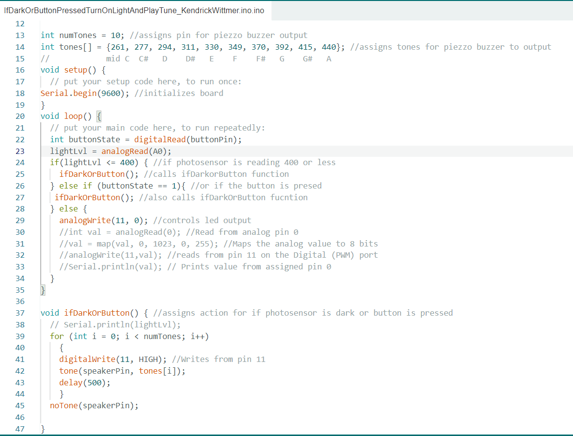
The first step after verifying the buzzer was connected was to assign integers for the inputs and outputs. This required the use of int and const int functions along with pin (i.e. speakerPin, buttonPin). The next few lines of code control the output sound for the piezo buzzer and was simply copied from the test snippet.
I then created a for function I could call as needed named ifDarkOrButton. This function controlled the response to if the photosensor went dark or the button was pressed. The function uses digitalwrite(11,high) to turn on the LED, tone(speakerPin, tones[i]) to play the scale on the buzzer, and delay(500). A noTone(speakerPin) function is used at the end to end the speaker scale.
I used a loop function for the main portion of this code. First, I assigned an integer for the button within the function (int buttonstate = digitalRead(buttonPin)) and then I assigned lightlvl to analog pin A0. An if function was then used to assign actions to the various inputs. First, if(lightlvl <=400) tells the arduino to do an action of the value printed from the photosensor drops below 400. Of course, said action was the ifDarkOrButton function which was typed on the next line. Then I utilized an else if function to control the response to the button being pressed, which looked like else if (buttonState == 1), activate the if DarkOrButton function.


Comments
Post a Comment